Welcome to the thread @BrattVapes look forward to seeing what you come up with. Lot of questions there so let me try and keep my answers short to stay on topic.
YES, Try and stick with the N channel mosfet, Could go further into the topic but lets start off with simple proven application.
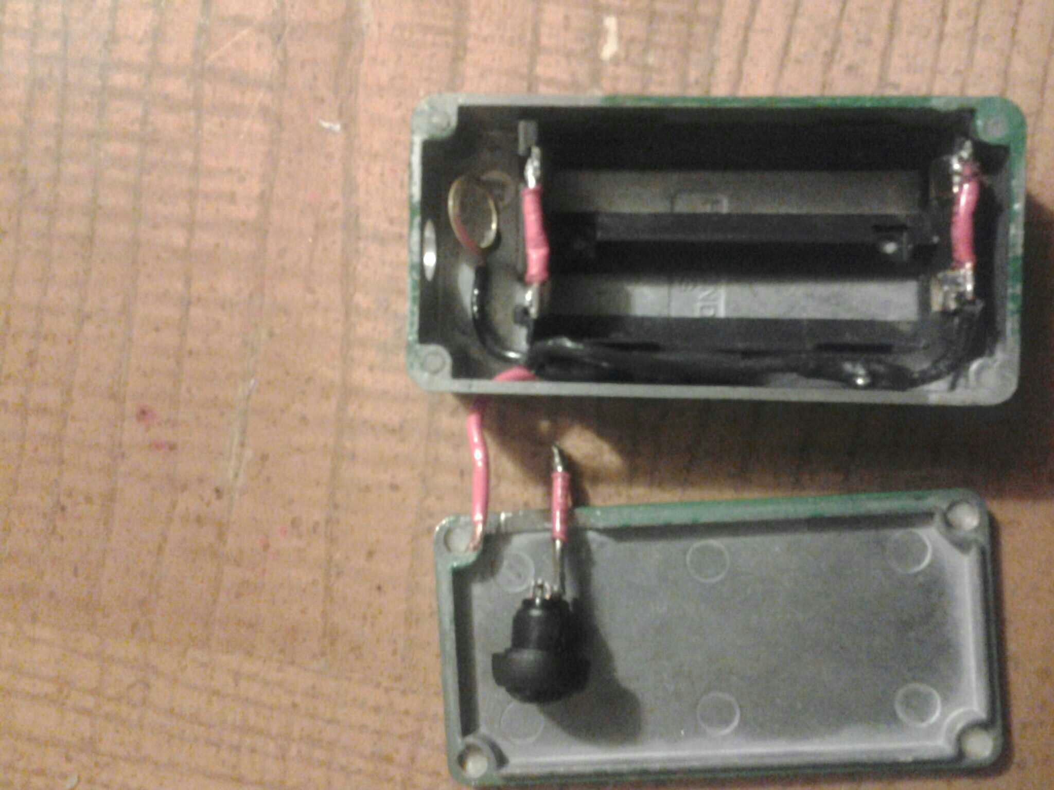
Most of us are using heat shrink to keep parts from touching causing shorts. Some use it to bolster the looks of the box inside. I tend to just use what is necessary, like the legs of the mosfets, if it's real tight i use more over the mosfet. Plastic boxes I just use on fet legs. Tape will work ok if you are not concerned about looks, but heatshrink is the preferred method.
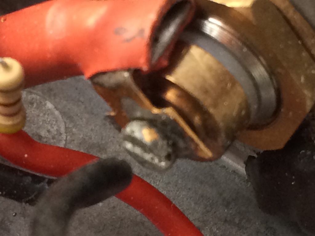
You MUST have the resistor working on that mosfet. That is used for closing the gate very fast after you let go of switch. With out it will let voltage through after button is pressed. MUST USE RESISTOR!!!
YES, Try and stick with the N channel mosfet, Could go further into the topic but lets start off with simple proven application.
Most of us are using heat shrink to keep parts from touching causing shorts. Some use it to bolster the looks of the box inside. I tend to just use what is necessary, like the legs of the mosfets, if it's real tight i use more over the mosfet. Plastic boxes I just use on fet legs. Tape will work ok if you are not concerned about looks, but heatshrink is the preferred method.
You MUST have the resistor working on that mosfet. That is used for closing the gate very fast after you let go of switch. With out it will let voltage through after button is pressed. MUST USE RESISTOR!!!

") . Russel.
. Russel.